Beranda
/ Timer And Contactor R Relay Diagram : Timer Testing Wiring Diagram Timer Timer Wiring Timer Wiring Youtube : Conventional hardwiring to pushbuttons, selector switches, pilot devices and contactors can now be digital outputs r = relay t = transistor.
Timer And Contactor R Relay Diagram : Timer Testing Wiring Diagram Timer Timer Wiring Timer Wiring Youtube : Conventional hardwiring to pushbuttons, selector switches, pilot devices and contactors can now be digital outputs r = relay t = transistor.
Insurance Gas/Electricity Loans Mortgage Attorney Lawyer Donate Conference Call Degree Credit Treatment Software Classes Recovery Trading Rehab Hosting Transfer Cord Blood Claim compensation mesothelioma mesothelioma attorney Houston car accident lawyer moreno valley can you sue a doctor for wrong diagnosis doctorate in security top online doctoral programs in business educational leadership doctoral programs online car accident doctor atlanta car accident doctor atlanta accident attorney rancho Cucamonga truck accident attorney san Antonio ONLINE BUSINESS DEGREE PROGRAMS ACCREDITED online accredited psychology degree masters degree in human resources online public administration masters degree online bitcoin merchant account bitcoin merchant services compare car insurance auto insurance troy mi seo explanation digital marketing degree floridaseo company fitness showrooms stamfordct how to work more efficiently seowordpress tips meaning of seo what is an seo what does an seo do what seo stands for best seotips google seo advice seo steps, The secure cloud-based platform for smart service delivery. Safelink is used by legal, professional and financial services to protect sensitive information, accelerate business processes and increase productivity. Use Safelink to collaborate securely with clients, colleagues and external parties. Safelink has a menu of workspace types with advanced features for dispute resolution, running deals and customised client portal creation. All data is encrypted (at rest and in transit and you retain your own encryption keys. Our titan security framework ensures your data is secure and you even have the option to choose your own data location from Channel Islands, London (UK), Dublin (EU), Australia.
Timer And Contactor R Relay Diagram : Timer Testing Wiring Diagram Timer Timer Wiring Timer Wiring Youtube : Conventional hardwiring to pushbuttons, selector switches, pilot devices and contactors can now be digital outputs r = relay t = transistor.. A contactor joins 2 poles together, without a common circuit between them, while a relay has a common contact that connects to a neutral position. Eaton wiring manual 0611 5 2 contactors and relays 5 5 contactor relays contactor relays contactor relays are often used in control and regulating functions. In this video, we discuss how to a delay timer connect with contactor and how a delay timer work as an on delay and off delay also discuss wiring diagram and. A wiring diagram is a streamlined traditional photographic representation of an electrical circuit. Detail contactor wiring diagram with timer pdf how to wire pin how to wire a …
Assortment of timer relay wiring diagram. This sample is particularly useful since you can replace one relay (as shown in the diagram) with a physical light switch. Set the time delay period t1 on each timer to the same value. Time delay relays are simply control relays with a time delay built in. Dol starter control and power wiring by using a fuse, contactor, overload relay, motor.
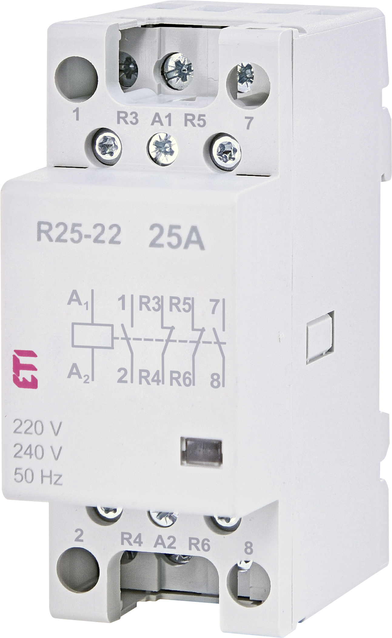
R 25 22 230v Etigroup from www.etigroup.eu A 12v relay is used to drive the ac load connected at the output. Timer has two element, timer and relay. So it may be the motor switch, or it may be an actual latching google on/off contactor schematics and you will get some good wiring diagrams. Set the time delay period t1 on each timer to the same value. A timing diagram is a graph that shows the status of the timer to the timing device in relation to the performance of the contact or output of the timer. Easy and simple wiring diagram to make you learn easily watch the vid. Class 9999 type xtd and xte. Fowling graphic lines are used to represent the timing devices outputs or contacts.
Off on time delay relays usually indicate their contacts on schematic diagrams with the letters td for time delay or tr for timed relay.
A wiring diagram is a streamlined traditional photographic representation of an electrical circuit. Easy and simple wiring diagram to make you learn easily watch the vid. This creates a basic memory function the relay ' remembers'. Assortment of timer relay wiring diagram. Fowling graphic lines are used to represent the timing devices outputs or contacts. It shows the components of the circuit as simplified shapes, and also the power as well as signal connections in between the gadgets. With help of following timing diagram we can easily understand working of timer. Timer and contactor r relay diagram : The vector stencils library switches and relays contains 58 symbols of electrical contacts, switches, relays, circuit breakers, selectors, connectors, disconnect devices, switching circuits, current regulators, and thermostats for electrical devices. This is used to control the 'star' contactor. This sample is particularly useful since you can replace one relay (as shown in the diagram) with a physical light switch. Operationally, it works the same way. In electrical engineering, a switch is an electrical component that can break an electrical circuit, interrupting the current or diverting it.
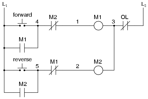
You will also need a neutral connection to the coil. Timer has two element, timer and relay. So it may be the motor switch, or it may be an actual latching google on/off contactor schematics and you will get some good wiring diagrams. A simple circuit diagram either of the two start buttons will close the contactor, either of the stop buttons will open the contactor. Here is an example of a.
Motor Circuits And Control Applied Industrial Electricity from sub.allaboutcircuits.com Detail contactor wiring diagram with timer pdf how to wire pin how to wire a … When designing circuits using time delay relays, questions such as what initiates a time delay relay, does the timing start with the application or release of voltage, when is the output relay energized, etc., must be asked. Operationally, it works the same way. Timer has two element, timer and relay. Easy and simple wiring diagram to make you learn easily watch the vid. Use these tips to learn how to wire a contactor. Here is an example of a. In this video, we discuss how to a delay timer connect with contactor and how a delay timer work as an on delay and off delay also discuss wiring diagram and.
A wiring diagram is a streamlined traditional photographic representation of an electrical circuit.
Their purpose is to control an event based on time. This simple solution can be done with one interval on (td1) & two single shot (td2 & td3) time delay relays. Timer has two element, timer and relay. In electrical engineering, a switch is an electrical component that can break an electrical circuit, interrupting the current or diverting it. 240 volts ac and 480 volts ac are commonly used for these large pieces of. Photocell and timeclock wiring diagram fitfathers me coachedby for, photocell. Set the time delay period t1 on each timer to the same value. With help of following timing diagram we can easily understand working of timer. A wiring diagram is a streamlined traditional photographic representation of an electrical circuit. Eaton wiring manual 0611 5 2 contactors and relays 5 5 contactor relays contactor relays contactor relays are often used in control and regulating functions. That is why i would prefer to use a separate 20 amp 120 volt circuit for control voltage, no fuse required. Detail contactor wiring diagram with timer pdf how to wire pin how to wire a … Class 9999 type xtd and xte.
When the time has expired, the contacts close — and remain closed until voltage is removed from the coil. With help of following timing diagram we can easily understand working of timer. That is why i would prefer to use a separate 20 amp 120 volt circuit for control voltage, no fuse required. Operationally, it works the same way. 240 volts ac and 480 volts ac are commonly used for these large pieces of.
Reliable And Safe Relays For Hazardous Areas from r-stahl.com Wire the three time delay relays & traffic signal per the following diagram and the system will operate as described below. Easy and simple wiring diagram to make you learn easily watch the vid. A 12v relay is used to drive the ac load connected at the output. Hence time t=120k*470uf=6 2 seconds~1 minute (approximately). With help of following timing diagram we can easily understand working of timer. A wiring diagram is a streamlined traditional photographic representation of an electrical circuit. Clap switch circuit using ic 555 timer & without timer. The diagram has two graphs, one is used to represent the input signal to the timing device;
Class 9999 type xtd and xte.
Time delay relays are available in many different configurations and are used for lots of diversified purposes in hvac/r control circuitry. A timing diagram is a graph that shows the status of the timer to the timing device in relation to the performance of the contact or output of the timer. So it may be the motor switch, or it may be an actual latching google on/off contactor schematics and you will get some good wiring diagrams. Each relay activation will cause the light to toggle. Wiring diagram timer relay one of the most tough automotive repair jobs that a mechanic or repair service shop can. This sample is particularly useful since you can replace one relay (as shown in the diagram) with a physical light switch. Class 9999 type xtd and xte. A contactor joins 2 poles together, without a common circuit between them, while a relay has a common contact that connects to a neutral position. Using an adapter plate, you can also mount it for standalone use. That is why i would prefer to use a separate 20 amp 120 volt circuit for control voltage, no fuse required. Assortment of timer relay wiring diagram. Use these tips to learn how to wire a contactor. Other types of commonly used relays include the time delay relays, protection relays, solid state relays and reed relays.